- 您现在的位置:买卖IC网 > Sheet目录369 > XRP7618IGBTR-F (Exar Corporation)IC LED DRVR 8CH CON CUR 20TSSOP
X R P 7 6 1 8
8 - C h a n n e l C o n s t a n t C u r r e n t L i n e a r L E D D r i v e r W i t h
S m a r t T a l k T M
THEORY OF OPERATION
The XRP7618 is an eight channel
programmable constant current LED driver
capable of up to 100mA per channel. A single
external resistor adjusts the current for each
channel over a 10mA to 100mA range with
tight matching between channels.
Dimming is supported through a standard
PWM scheme or through an analog signal.
Furthermore, the XRP7618 maximizes the
overall system efficiency by dynamically
reporting the minimum LED voltage necessary
to remain in current regulation mode when
used with a boost converter.
Multiple XRP7618s can be placed in parallel to
drive over 8 strings of LEDs; however, unused
channels should be tied to ground.
Built-in under voltage lock out, open LED and
over temperature protections insure safe
operations under abnormal operating
conditions.
LED C HANNELS C URRENT S ETTING
The maximum LED current can be set up to
100mA per channel through the ISET pin. To
set the reference current I SET , connect a
resistor R SET between this pin and ground. The
value of R SET can be calculated by the following
formula:
This reference current is multiplied internally
with a gain (K) of 400 then mirrored on all
enabled channels. This sets the maximum LED
current, referred to as 100% current (I LEDMAX ).
The value can be calculated by the following
formula:
or,
The LED current can be reduced from 100%
by PWM dimming control.
PWM D IMMING C ONTROL
The LED current can be adjusted by applying a
PWM signal to the PWM pin. In this mode, all
enabled channels are adjusted at the same
time and brightness is adjusted from 1% to
100% of I LEDMAX .
The supported external PWM signal frequency
is 100Hz to 25kHz.
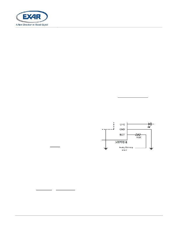
A NALOG D IMMING CONTROL
Besides PWM dimming control, the LED
current can be controlled continuously (from
highest to lowest LED current) by raising the
voltage at the bottom of RSET from 0V
normally to 1V max, respectively. RSET value
may be determined as
where, 1.194V is a typical ISET pin voltage,
VMOD is an adjustment voltage applied to the
bottom side of RSET, 400 is the typical current
multiplication ratio, and I LEDMAX is the required
LED current per channel.
Fig. 10: XRP7618 Analog Dimming Control
If adjustment voltage VMOD isn’t used, RSET
resistor should be connected to ground.
S YSTEM P OWER O PTIMIZATION
The Smart Talk feature enables XRP7618 to
maximize the overall system power efficiency,
when used with a step-up converter, by
dynamically reporting the minimum LED
channel voltage needed to maintain current
regulation mode. The XRP7618 samples the
voltage on each channel input and reports the
lowest voltage of all strings via the FB signal
to the associated step up converter.
If placed in shutdown through the EN pin or if
all channels are inactive, the XRP7618 outputs
? 2013 Exar Corporation
6/10
Rev. 1.2.0
发布紧急采购,3分钟左右您将得到回复。
相关PDF资料
XRP7620IH-F
IC LED SINK DVR I2C 4CH 8DFN
XRP7714EVB
EVAL BAORD FOR XRP7714
XRP77XXEVB-XCM
EVAL BOARD W/USB-I2C FOR XRP7704
YRDKRL78G13
KIT DEV RSK FOR RL78G13
YRDKRX62N
KIT DEMO FOR RX62N MCU LOW COST
YRDKSH7216W
BOARD DEVELOPMENT FOR SH7216
ZA1010
PLUG AUTO PWR BLACK W/O LED IND
ZA1030
CIGARETTE PLUG BAKELITE
相关代理商/技术参数
XRP7620
制造商:EXAR 制造商全称:EXAR 功能描述:4-Channel Adjustable Current I2C Controlled LED Driver
XRP7620EVB
功能描述:电源管理IC开发工具 Eval Board for XRP7620 Series RoHS:否 制造商:Maxim Integrated 产品:Evaluation Kits 类型:Battery Management 工具用于评估:MAX17710GB 输入电压: 输出电压:1.8 V
XRP7620IH-F
功能描述:LED照明驱动器 4-Chan Independently Adj. Curr Sink Drivr RoHS:否 制造商:STMicroelectronics 输入电压:11.5 V to 23 V 工作频率: 最大电源电流:1.7 mA 输出电流: 最大工作温度: 安装风格:SMD/SMT 封装 / 箱体:SO-16N
XRP7620IHTR-F
功能描述:LED照明驱动器 4-Chan Independently Adj. Curr Sink Drivr RoHS:否 制造商:STMicroelectronics 输入电压:11.5 V to 23 V 工作频率: 最大电源电流:1.7 mA 输出电流: 最大工作温度: 安装风格:SMD/SMT 封装 / 箱体:SO-16N
XRP7657ED-F
制造商:Exar Corporation 功能描述:IC REGULATOR STED DOWN 2A 25V
XRP7657EDTR-F
功能描述:电压模式 PWM 控制器 2A 25V Non Sync. Step Down Reg. RoHS:否 制造商:Texas Instruments 输出端数量:1 拓扑结构:Buck 输出电压:34 V 输出电流: 开关频率: 工作电源电压:4.5 V to 5.5 V 电源电流:600 uA 最大工作温度:+ 125 C 最小工作温度:- 40 C 封装 / 箱体:WSON-8 封装:Reel
XRP7657EVB
功能描述:电源管理IC开发工具 Eval Board for XRP7657 Series RoHS:否 制造商:Maxim Integrated 产品:Evaluation Kits 类型:Battery Management 工具用于评估:MAX17710GB 输入电压: 输出电压:1.8 V
XRP7659
制造商:EXAR 制造商全称:EXAR 功能描述:1.5A 18V1.4MHz Non Synchronous Step-Down Regulator
